Thermit Welding | Rail Alumino–Thermic Welding | Thermite Welding Procedure :: TheMech.in
Thermit welding steps:
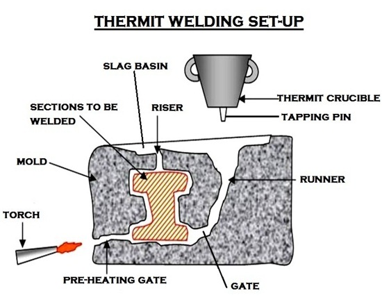
Various steps involved in the non pressure fusion thermit welding of metal parts is explained below. The mold is non-repetitive in nature and is used for repair welds.
1. Clean the joint:
An oxy-acetylene torch may be used to clean the metal surfaces by heating. During cleaning all dirt, grease, loose oxides, scale etc., must be removed.
2. Allow for contraction:
After cleaning, the part to be welded are to be lined up with a space of about 1.5 to 6 mm between the ends, depending upon the size of the parts to be joined.
This space makes you for
i. The contraction of the thermit steel in cooling
ii. The shrinkage of the base metal which has been heated during the welding operation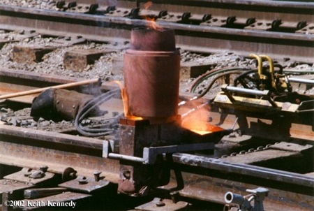
3. Construct the mold:
After the parts have been cleaned and spaced properly, the next stage is the making of the wax pattern from which the mould will be formed and which must in shape constitude a replica of the eventual weld.
The molding materials should be about 100 mm thick between the wax pattern and the molding box at all points.
The mold should be provided with the necessary number of pouring gates, heating gates and risers depending on the size of the weld.
4. Preheating the mold:
The mold prepared as above is then preheated in order to:
i. Melt away and remove the wax thereby leaving a mold cavity in the exact shape of the weld.
ii. Dry the mold thoroughly otherwise the superheated molten metal will form steam within the mold and cause porous weld.
5. Crucible and its charging:
Thermit mixture is charged in the container knows as crucible or reaction vessel. This vessel is of conical shape and is lined with magnesia tar lining.
The outside shell of this vessel is made up of steel sheet. Located at the bottom of the vessel is a magnesia stone and magnesia thimble through which the tapping pin is suspended.
The thimble is plugged by suspending the tapping pin through the thimble and placing a metal disc above the pin. This disc is then covered with refractory sand.
After drying the crucible, a small quantity of the thermit powder is first introduced, the object being to avoid damage to the refractory sand layer and to cushion off the plugging material in the bottom of the crucible from the impact of the full weight of the thermit charge.
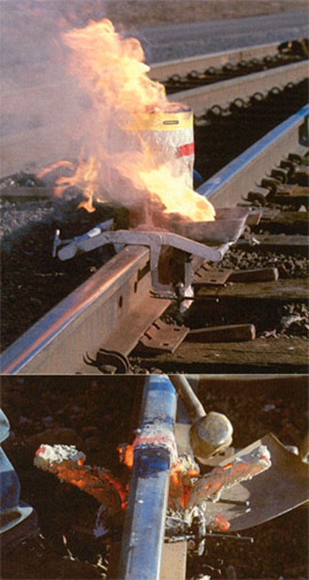
6. Igniting the thermit mixture:
A low ignition point thermit in the form of a powder is placed on the top of the thermit in the crucible.
To initiate the reaction, the low ignition – temperature thermit is contacted with a hot rod. This ignition immediately starts the reaction in the main thermit charge.
7. Opening the mold:
The actual period for which the mold is left unopened depends upon the dimensions of the weld, being shorter (2 to 3 hours) for small sections and longer (about 4 hours) for heavy sections. The longer the mould can be left unopened, the better it is.
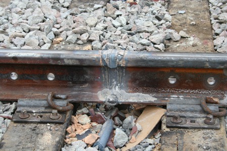
8. Finishing the weld:
After removing the mold, the risers and gates are cut away with a cutting torch. In case of shafts or parts requiring specific finished contour the same can be given by either machining and grinding.
——————————————————————
Tagged with: Aluminium thermite • exothermic welding • railroad welding • thermit welding pdf • thermite casting • thermite sparking • thermite temperature • thermite torch • Thermite Welding • thermite welding procedure • welding steel • what is thermit welding
-
 Mechanical properties for mechanical engineering and design
Mechanical Properties The mechanical properties of a material describe
-
 Being inside a Porsche engine factory is like being inside a Transformer
This video is fascinating because it let’s us
-
 Pro/ENGINEER Interview Questions and Answers
Pro/ENGINEER [Pro-E] 1. What is the difference between object
Leave a Reply