What Is Geometric Dimensioning and Tolerancing [GD&T] and Symbols
What Is GD&T?
GD&T stands for geometric dimensioning and tolerancing. It is a system of symbols, rules and definitions used to define the geometry of mechanical parts.
GD&T is one of the most powerful tools available that can improve quality, reduce cost and shorten delivery time. All of this is possible when the concurrent engineering team is involved with the creation of the drawing. The drawing is a common thread that ties these groups together.
They all are involved with the engineering drawing. GD&T on the drawing must first and foremost capture design intent. However, the best design in the world is worthless if it cannot be produced.
That is why it is necessary for production/vendors and quality to be involved with the requirements that are placed on the drawing. When they are not involved, the drawings often have overly tight tolerances and result in non-producible parts. At least not producible at the quality level, cost and timeliness expected by industry.
Nearly every company in the United States and many companies around the world use the ASME Y14.5M- 1994 standard on GD&T. There is an ISO standard but it is in a state of flux. Because of this the Y14.5 standard is recognized and used around the world.
In short, GD&T is:
· Symbols
· Rules
· Vocabulary
· Mathematical definition (ASME Y14.5.1)
· A National Standard (ASME Y14.5M-1994)
· An International Standard (ISO 1101)
There is no other standardized way to control the geometry of parts. The old methods were never standardized. Many people thought they knew what the old method meant. The problem was that many people interpreted the drawing differently. GD&T is standardized and mathematized which means that anyone who knows the Standard, knows what the drawing means. GD&T is today’s
Print Reading. Anyone who creates, approves or uses the drawing should know how to read the drawing. In today’s world, if you do not know GD&T, you do not know how to read!
GD&T Glossary and Resource Symbols and Terms
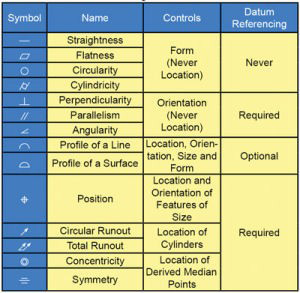
Use this quick reference to find definitions of common GD&T symbols and terms. Our full color Pocket Guide is a great resources for your desk, workbench or pocket. Be sure to check out our GD&T Tips!
![]() All Around Symbol – indicating that a tolerance applies to surfaces all around the part.
All Around Symbol – indicating that a tolerance applies to surfaces all around the part.
![]() All Over Specification [ASME Y14.5-2009 Section 8.3.1.6] – In addition to a general profile of a surface tolerance there is the option of specifying that the tolerance applies all over on the field of the drawing. It is important to realize that this specification, whether in a general note or on the field of the drawing, applies UNLESS OTHERWISE SPECIFIED.
All Over Specification [ASME Y14.5-2009 Section 8.3.1.6] – In addition to a general profile of a surface tolerance there is the option of specifying that the tolerance applies all over on the field of the drawing. It is important to realize that this specification, whether in a general note or on the field of the drawing, applies UNLESS OTHERWISE SPECIFIED.
 All Around This Side of Parting Line [ ASME Y14.5-2009 Section 3.14.1] – To apply a requirement to all features all around one side of a parting line, the graphical symbol for all around this side of parting line is indicated on the leader line.
 All Over This Side of Parting Line [ ASME Y14.5-2009 Section 3.14.2] – To apply a requirement to all features all over one side of a parting line, the graphical symbol for all over this side of parting line is indicated on the leader line.
![]() Angularity – is the condition of a surface, axis, or centerplane, which is at a specified angle from a datum plane or axis.
Angularity – is the condition of a surface, axis, or centerplane, which is at a specified angle from a datum plane or axis.
![]() Arc Length – indicating that a dimension is an arc length measured on a curved outline. The symbol is placed above the dimension.
Arc Length – indicating that a dimension is an arc length measured on a curved outline. The symbol is placed above the dimension.
![]() Basic Dimension – used to describe the exact size, profile, orientation or location of a feature. A basic dimension is always associated with a feature control frame or datum target. (Theoretically exact dimension in ISO)
Basic Dimension – used to describe the exact size, profile, orientation or location of a feature. A basic dimension is always associated with a feature control frame or datum target. (Theoretically exact dimension in ISO)
![]() Between – to indicate that a profile tolerance applies to several contiguous features, letters may designate where the profile tolerance begins and ends. These letters are referenced using the between symbol (since 1994) or the word between on drawings made to earlier versions of the Standard.
Between – to indicate that a profile tolerance applies to several contiguous features, letters may designate where the profile tolerance begins and ends. These letters are referenced using the between symbol (since 1994) or the word between on drawings made to earlier versions of the Standard.
![]() Concentricity – describes a condition in which two or more features , in any combination, have a common axis.
Concentricity – describes a condition in which two or more features , in any combination, have a common axis.
![]() Conical Taper – is used to indicate taper for conical tapers. This symbol is always shown with the vertical leg to the left.
Conical Taper – is used to indicate taper for conical tapers. This symbol is always shown with the vertical leg to the left.
![]() Continuous Feature [ASME Y14.5-2009 Section 2.7.5] – The note CONTINUOUS FEATURE or the continuous feature symbol is used to identify a group of two or more features of size where there is a requirement that they be treated geometrically as a single feature of size. Although the definition only mentions features of size, there is an example of CF being applied to a pair of planar features.
Continuous Feature [ASME Y14.5-2009 Section 2.7.5] – The note CONTINUOUS FEATURE or the continuous feature symbol is used to identify a group of two or more features of size where there is a requirement that they be treated geometrically as a single feature of size. Although the definition only mentions features of size, there is an example of CF being applied to a pair of planar features.
![]() Controlled Radius – creates a tolerance zone defined by two arcs (the minimum and maximum radii) that are tangent to the adjacent surfaces. Where a controlled radius is specified, the part contour within the crescent-shaped tolerance zone must be a fair curve without flats or reversals. Additionally, radii taken at all points on the part contour shall neither be smaller than the specified minimum limit nor larger than the maximum limit.
Controlled Radius – creates a tolerance zone defined by two arcs (the minimum and maximum radii) that are tangent to the adjacent surfaces. Where a controlled radius is specified, the part contour within the crescent-shaped tolerance zone must be a fair curve without flats or reversals. Additionally, radii taken at all points on the part contour shall neither be smaller than the specified minimum limit nor larger than the maximum limit.
![]() Counterbore/Spotface – is used to indicate a counterbore or a spotface. The symbol precedes the dimension of the counterbore or spotface, with no space.
Counterbore/Spotface – is used to indicate a counterbore or a spotface. The symbol precedes the dimension of the counterbore or spotface, with no space.
![]() Countersink – is used to indicate a countersink. The symbol precedes the dimensions of the countersink with no space.
Countersink – is used to indicate a countersink. The symbol precedes the dimensions of the countersink with no space.
![]() Cylindricity – describes a condition of a surface of revolution in which all points of a surface are equidistant from a common axis.
Cylindricity – describes a condition of a surface of revolution in which all points of a surface are equidistant from a common axis.
![]() Datum Feature – is the actual component feature used to establish a datum.
Datum Feature – is the actual component feature used to establish a datum.
![]() Datum Target – is a specified point, line, or area on a part that is used to establish the Datum Reference Plane for manufacturing and inspection operations.
Datum Target – is a specified point, line, or area on a part that is used to establish the Datum Reference Plane for manufacturing and inspection operations.
![]() Depth/Deep – is used to indicate that a dimension applies to the depth of a feature. This symbol precedes the depth value with no space in between.
Depth/Deep – is used to indicate that a dimension applies to the depth of a feature. This symbol precedes the depth value with no space in between.
![]() Diameter – indicates a circular feature when used on the field of a drawing or indicates that the tolerance is diametrical when used in a feature control frame.
Diameter – indicates a circular feature when used on the field of a drawing or indicates that the tolerance is diametrical when used in a feature control frame.
![]() Dimension Origin – Signifies that the dimension originates from the plane established by the shorter surface and dimensional limits apply to the other surface.
Dimension Origin – Signifies that the dimension originates from the plane established by the shorter surface and dimensional limits apply to the other surface.
![]() Feature Control Frame – is a rectangular box containing the geometric characteristics symbol, and the form, runout or location tolerance. If necessary, datum references and modifiers applicable to the feature or the datums are also contained in the box.
Feature Control Frame – is a rectangular box containing the geometric characteristics symbol, and the form, runout or location tolerance. If necessary, datum references and modifiers applicable to the feature or the datums are also contained in the box.
![]() Flatness – is the condition of a surface having all elements in one plane.
Flatness – is the condition of a surface having all elements in one plane.
![]() Free State Variations – is a term used to describe distortion of a part after removal of forces applied during manufacture.
Free State Variations – is a term used to describe distortion of a part after removal of forces applied during manufacture.
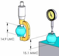
![]() Least Material Condition (LMC) – implies that condition of a part feature of size wherein it contains the least (minimum) amount of material, examples, largest hole size and smallest shaft size. It is opposite to maximum material condition.
Least Material Condition (LMC) – implies that condition of a part feature of size wherein it contains the least (minimum) amount of material, examples, largest hole size and smallest shaft size. It is opposite to maximum material condition.
![]() Independency Symbol [ASME Y14.5-2009 Section 2.7.3] – The Independency symbol is applied to the size dimension in order to invoke the principle of independency to regular features of size and override Rule #1.
Independency Symbol [ASME Y14.5-2009 Section 2.7.3] – The Independency symbol is applied to the size dimension in order to invoke the principle of independency to regular features of size and override Rule #1.
![]() Maximum Material Condition (MMC)– is that condition of a part feature wherein it contains the maximum amount of material within the stated limits of size. That is: minimum hole size and maximum shaft size.
Maximum Material Condition (MMC)– is that condition of a part feature wherein it contains the maximum amount of material within the stated limits of size. That is: minimum hole size and maximum shaft size.
![]() Movable Datum Targets [ASME Y14.5-2009 Section 4.24.6] – The movable datum target symbol may be used to indicate movement of the datum target datum feature simulator.
Movable Datum Targets [ASME Y14.5-2009 Section 4.24.6] – The movable datum target symbol may be used to indicate movement of the datum target datum feature simulator.
![]() Number of Places – the X is used along with a value to indicate the number of times a dimension or feature is repeated on the drawing.
Number of Places – the X is used along with a value to indicate the number of times a dimension or feature is repeated on the drawing.
![]() Parallelism – is the condition of a surface, line, or axis, which is equidistant at all points from a datum plane or axis.
Parallelism – is the condition of a surface, line, or axis, which is equidistant at all points from a datum plane or axis.
![]() Parting Lines [ASME Y14.5-2009 Section 3.14] – are depicted on casting/forging/molded part drawings as a phantom line extending beyond the part in applicable views, with the parting line symbol added.
Parting Lines [ASME Y14.5-2009 Section 3.14] – are depicted on casting/forging/molded part drawings as a phantom line extending beyond the part in applicable views, with the parting line symbol added.
![]() Perpendicularity – is the condition of a surface, axis, or line, which is 90 deg. From a datum plane or a datum axis.
Perpendicularity – is the condition of a surface, axis, or line, which is 90 deg. From a datum plane or a datum axis.
![]() Position Tolerance – defines a zone within which the axis or center plane of a feature is permitted to vary from true (theoretically exact) position.
Position Tolerance – defines a zone within which the axis or center plane of a feature is permitted to vary from true (theoretically exact) position.
![]() Profile of a Line – is the condition permitting a uniform amount of profile variation, ether unilaterally or bilaterally, along a line element of a feature.
Profile of a Line – is the condition permitting a uniform amount of profile variation, ether unilaterally or bilaterally, along a line element of a feature.
![]() Profile of a Surface – is the condition permitting a uniform amount of profile variation, ether unilaterally or bilaterally, on a surface.
Profile of a Surface – is the condition permitting a uniform amount of profile variation, ether unilaterally or bilaterally, on a surface.
![]() Projected Tolerance Zone – applies to a hole in which a pin, stud, screw, etc., is to be inserted. It controls the perpendicularity of the hole to the extent of the projection from the hole and as it relates to the mating part clearance. The projected tolerance zone extends above the surface of the part to the functional length of the pin, stud, and screw relative to its assembly with the mating part.
Projected Tolerance Zone – applies to a hole in which a pin, stud, screw, etc., is to be inserted. It controls the perpendicularity of the hole to the extent of the projection from the hole and as it relates to the mating part clearance. The projected tolerance zone extends above the surface of the part to the functional length of the pin, stud, and screw relative to its assembly with the mating part.
![]() Radius – creates a zone defined by two arcs (the minimum and maximum radii). The part surface must lie within this zone.
Radius – creates a zone defined by two arcs (the minimum and maximum radii). The part surface must lie within this zone.
![]()
- Reference Dimension – a dimension usually without tolerance, used for information purposes only. It does not govern production or inspection operations. (Auxiliary dimension in ISO)
- Regardless Of Feature Size (RFS) – the condition where the tolerance of form, runout or location must be met irrespective of where the feature lies within its size tolerance.
![]() Roundness – describes the condition on a surface of revolution (cylinder, cone, sphere) where all points of the surface intersected by any plane.
Roundness – describes the condition on a surface of revolution (cylinder, cone, sphere) where all points of the surface intersected by any plane.
![]() Runout – is the composite deviation from the desired form of a part surface of revolution through on full rotation (360 deg) of the part on a datum axis.
Runout – is the composite deviation from the desired form of a part surface of revolution through on full rotation (360 deg) of the part on a datum axis.
![]() Slope – is used to indicate slope for flat tapers. This symbol is always shown with the vertical leg to the left.
Slope – is used to indicate slope for flat tapers. This symbol is always shown with the vertical leg to the left.
![]() Spherical Diameter – shall precede the tolerance value where the specified tolerance value represents spherical zone. Also, a positional tolerance may be used to control the location of a spherical feature relative to other features of a part. The symbol for spherical diameter precedes the size dimension of the feature and the positional tolerance value, to indicate a spherical tolerance zone.
Spherical Diameter – shall precede the tolerance value where the specified tolerance value represents spherical zone. Also, a positional tolerance may be used to control the location of a spherical feature relative to other features of a part. The symbol for spherical diameter precedes the size dimension of the feature and the positional tolerance value, to indicate a spherical tolerance zone.
![]() Spherical Radius – precedes the value of a dimension or tolerance.
Spherical Radius – precedes the value of a dimension or tolerance.
![]() Spotface [ASME Y14.5-2009 Section 1.8.14] – Counterbore and spotface previously used the same symbol. A spotface now looks like the counterbore symbol with the addition of the letters SF.
Spotface [ASME Y14.5-2009 Section 1.8.14] – Counterbore and spotface previously used the same symbol. A spotface now looks like the counterbore symbol with the addition of the letters SF.
![]() Square – is used to indicate that a single dimension applies to a square shape. The symbol precedes the dimension with no space between.
Square – is used to indicate that a single dimension applies to a square shape. The symbol precedes the dimension with no space between.
![]() Statistical Tolerance – is the assigning of tolerances to related components of an assembly on the basis of sound statistics (such as the assembly tolerance is equal to the square root of the sum of the squares of the individual tolerances). By applying statistical tolerancing, tolerances of individual components may be increased or clearances between mating parts may be reduced. The increased tolerance or improved fit may reduce manufacturing cost or improve the product’s performance, but shall only be employed where the appropriate statistical process control will be used. Therefore, consideration should be given to specifying the required Cp and /or Cpk or other process performance indices.
Statistical Tolerance – is the assigning of tolerances to related components of an assembly on the basis of sound statistics (such as the assembly tolerance is equal to the square root of the sum of the squares of the individual tolerances). By applying statistical tolerancing, tolerances of individual components may be increased or clearances between mating parts may be reduced. The increased tolerance or improved fit may reduce manufacturing cost or improve the product’s performance, but shall only be employed where the appropriate statistical process control will be used. Therefore, consideration should be given to specifying the required Cp and /or Cpk or other process performance indices.
![]() Straightness – a condition where an element of a surface or an axis is a straight line.
Straightness – a condition where an element of a surface or an axis is a straight line.
![]() Symmetry – is a condition in which a feature (or features) is symmetrically disposed about the center plane of a datum feature.
Symmetry – is a condition in which a feature (or features) is symmetrically disposed about the center plane of a datum feature.
![]() Tangent Plane – indicating a tangent plane is shown. The symbol is placed in the feature control frame following the stated tolerance.
Tangent Plane – indicating a tangent plane is shown. The symbol is placed in the feature control frame following the stated tolerance.
![]() Target Point – indicates where the datum target point is dimensionally located on the direct view of the surface.
Target Point – indicates where the datum target point is dimensionally located on the direct view of the surface.
![]() Total Runout – s the simultaneous composite control of all elements of a surface at all circular and profile measuring positions as the part is rotated through 360.
Total Runout – s the simultaneous composite control of all elements of a surface at all circular and profile measuring positions as the part is rotated through 360.
![]() Datum Translation Symbol [ASME Y14.5-2009 Section 3.3.26 ] – This symbol indicates that a datum feature simulator is not fixed at its basic location and shall be free to translate.
Datum Translation Symbol [ASME Y14.5-2009 Section 3.3.26 ] – This symbol indicates that a datum feature simulator is not fixed at its basic location and shall be free to translate.
 Unilateral and Unequally Disposed Profile Tolerance [ASME Y14.5-2009 Section 8.3.1.2] – To indicate that a profile of a surface tolerance is not symmetrical about the true profile, this symbol is used. The first value in the feature control frame is the total width of the profile tolerance. The value following the symbol is the amount of the tolerance that is in the direction that would allow additional material to be added to the true profile.
|
What Is Geometric Dimensioning and Tolerancing [GD&T] and Symbols.pdf
|
|
-
 Five less expensive CAD applications
There are a number of other less expensive CAD
-
 Mechanical properties for mechanical engineering and design
Mechanical Properties The mechanical properties of a material describe
-
 Gorilla Glass Manufacturing Process | Gorilla Glass Strength Test | Gorilla Glass Molding :: TheMech.in
Touch screen technology in fast few years has grown
hey